New Member
Posted: 28 Oct 2014, 19:46
Hi all
It's been inlightning look through your forum - excellent stuff.
I have recently purchased a CRM250 Mk 2 with high hopes of restoring, most of the bike is in tack, apart from a jumble of wires, that have been completely butchered. I decided before any restore I would get the bike fire up.
I really hope you can help on this or at least throw some light on it.
The PGM, REC, CONDENSER, COIL are all there and a strike of luck the plug for the cdi was there also with 14 wires showing asuming these components are all correct I have a part of the loom - the only plug was the one with 3 yellows which I have plugged into the generator.
So from I decided to check out the diagram's and after trolling the web, came up with a few, but concentrated on the Mk2/Mk3 diagram - and started to try and work it out after a few hours of head scratching.
Not sure whats wrong - but the diagram's cdi wiring order - does not seem to relate to the cdi plug that I have - I have attached a couple of images
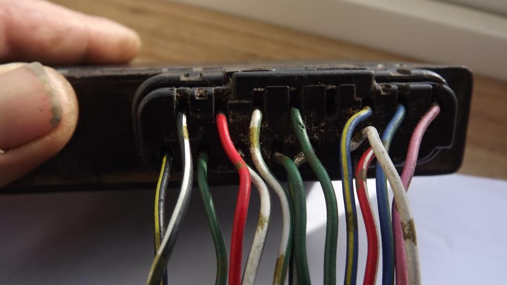
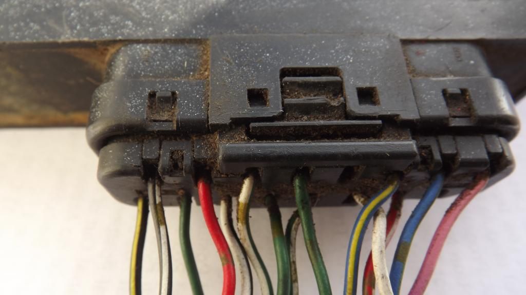
maybe this is norm, but seemed a bit strange - especially if you need to start building a loom from scratch.
After wiring things up - what a surprise no spark - check reg and volts enough to light a test lamp. so seemed ok on that side of things.
I have not connected the wires that seem to be the servo wires - I assume these are not needed to get a fire up.
The green white strip I think is the stand wire - I did put this to ground, but then felt maybe it's ground that kills the spark, so tried both connected and totally disconnected. not sure on this one!!
The black/white I take as the ignition and kill switch - I connected them to the red side from reg and condenser to bypass.
I took it that the blue/yellow and white gold dots to stator ' trigger coils.
The loom has 3 greens all the same bit confusing - one to the stator - one to coil and the other to ground. but in what order not sure! very puzzled.
The diagram shows that the Black and Yellow strip wire also go to coil - strange thing is that wire shows common with ground (earth) just seems to be a bit odd - would that point to a faulty cdi box? or is it not the power wire?
Or is it that the wiring plug and PGM(CDI) are not compatable?
I hope I have not posted this in the wrong place, would not like to get my wrist slapped this soon
